Oct 2024 – Mar 2025
Low-Level LCD Driver for GC9203
A C++ driver for the GC9203 LCD written from the datasheet, using an 8-bit indexed framebuffer and partial refresh to cut RAM footprint nearly in half on an ESP8266.
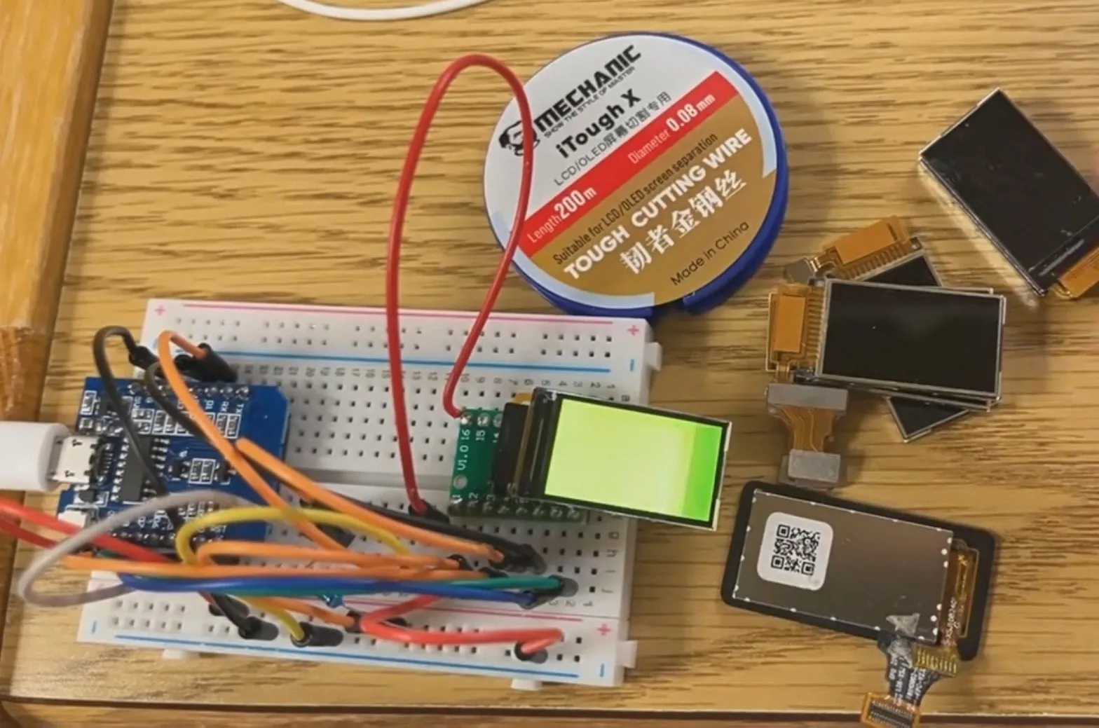
Overview
A C++ driver for the GC9203 LCD controller, written from the datasheet with no graphics library, and tested on an ESP8266. It provides pixel, line, rectangle, and fill primitives on top of a compact framebuffer.
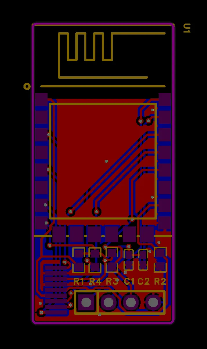
Breakout board
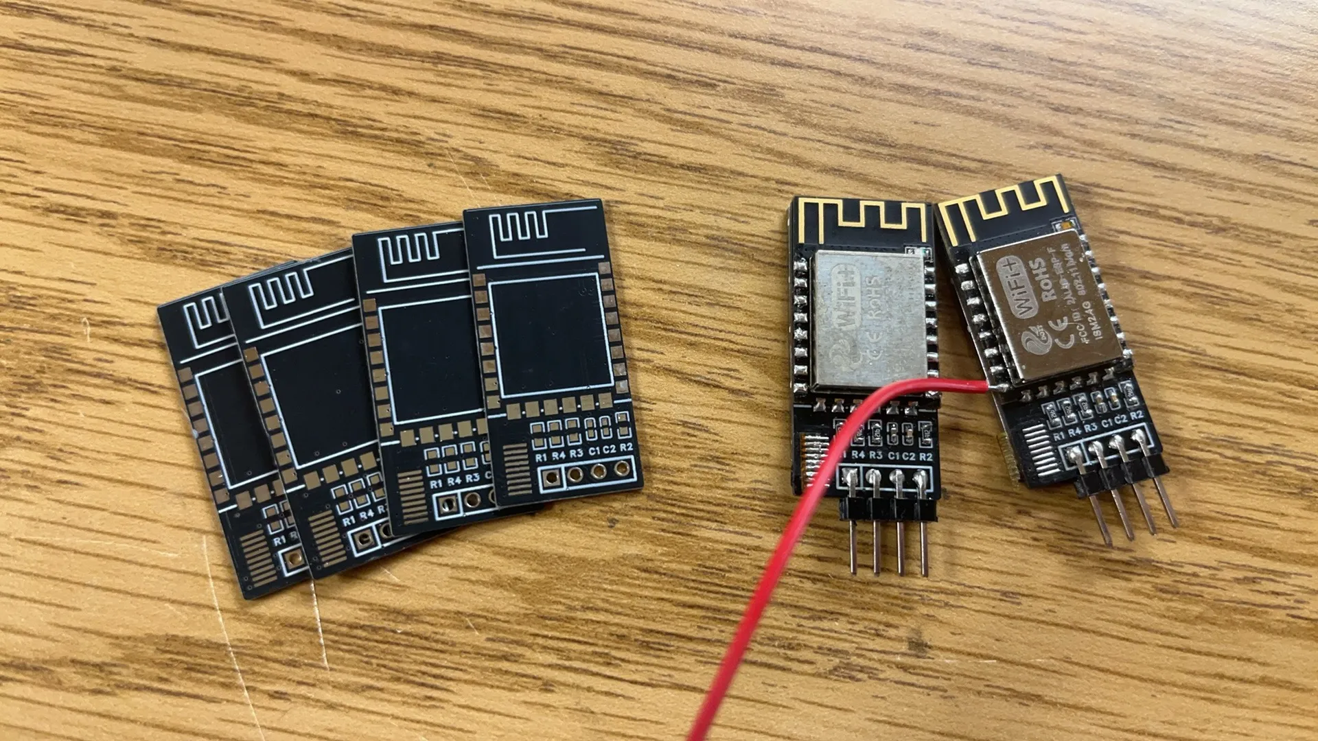
I designed a small ESP8266 breakout board in Altium Designer, had it fabricated by JLCPCB, then assembled the modules and tested them with the driver.
Bring-up
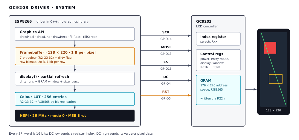
Every SPI word is 16 bits. With DC low, the word selects a register. With DC high, it writes that register’s value or pixel data.
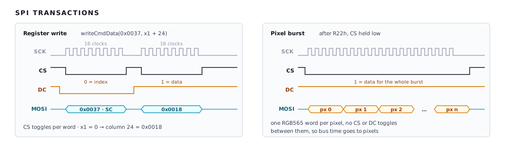
The display stayed blank on the first attempt. A logic analyzer on SCK, MOSI, CS, and DC showed the command timing and framing did not match the datasheet. I fixed the initialization sequence by comparing the captures with the datasheet’s timing diagrams.
Address window
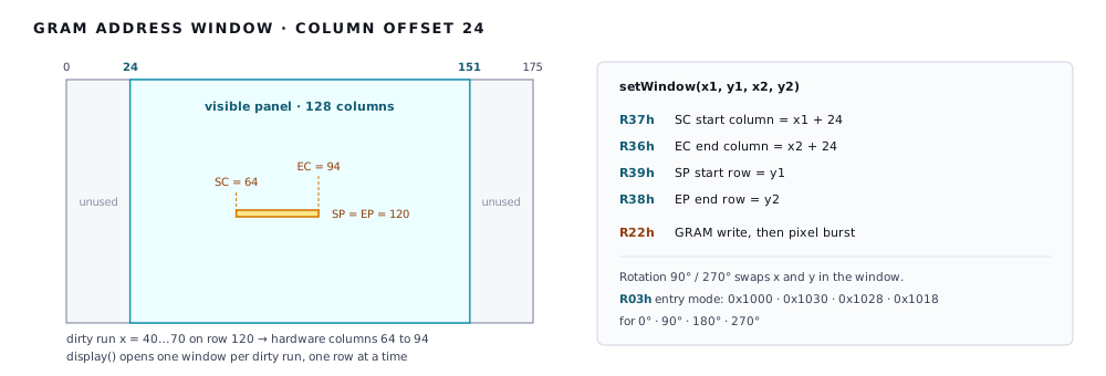
The GC9203 addresses 176 columns, and the 128-pixel panel sits in the middle. Every column written gets a base offset of 24. Rotation changes the entry mode and swaps x and y in the window.
Saving RAM
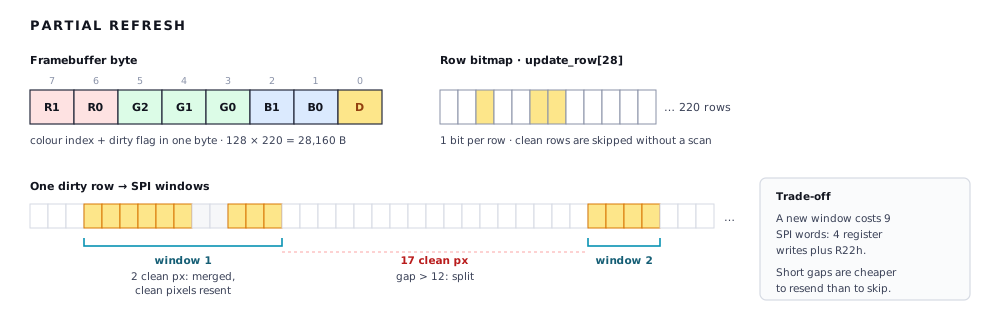
A full RGB565 framebuffer was too large for the ESP8266. Instead, each pixel is one byte: a 7-bit colour index plus a dirty flag. A 256-entry lookup table expands the colour to RGB565 on the way out. display() skips clean rows using a 28-byte bitmap and sends each dirty run as one window and one burst. This cut RAM from 56.3 KB (128 × 220 × 2 B) to 28.7 KB (28,160 B framebuffer + 512 B LUT + 28 B bitmap), a 49% reduction.
Register map
Every register the driver writes, for reference.
| Reg | Name | Value | Purpose |
|---|---|---|---|
FEh, FFh | Vendor unlock | none | Sent first, before any other register |
01h | Driver output control | 0x001C | Output setup, from the datasheet |
03h | Entry mode | 0x1000 to 0x1018 | GRAM write direction, set per rotation |
05h | SPI 2-data | 0x0000 | Single-line SPI |
07h | Display control 1 | 0x0013 | Display on, written last |
08h | Display control 2 | 0x0404 | Front and back porch |
0Fh | Oscillator control | 0x0701 | Oscillator setup |
10h | Power control 1 | 0x0000 | Exit standby |
11h | Power control 2 | 0x1000 | Auto boost, then wait 120 ms |
30h | Gate scan control | 0x0000 | Gate scan setup |
36h to 39h | Window EC, SC, EP, SP | per draw | GRAM address window |
22h | GRAM write | none | Pixel data follows |
Power-up order: reset low 10 ms, high 120 ms, unlock, configure, power on, wait 120 ms, display on.